
Pilotshop.com
- Shop All Categories
- Browse Headsets


- Photo may represent series and not specific product
- SHARE


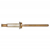
Hydro-Shift Cherrylock Riveter
MFR Model# G689
 FREE Shipping
- JUMP TO
- Overview
- Specifications
- Reviews
- Q&A
Overview
|
The Cherry G689 Hydro-Shift Riveter is a heavy duty pneumatic-hydraulic tool designed specifically for the installation of all CherryLOCK® Rivets. The G689 is recom-mended primarily for 1/4" diameter CherryLOCK® rivets. It can be used to install all diameters and lengths as indicated on the tool capacity charts. Its durable, all metal housing makes this tool very robust for use in a shop environment. This extremely powerful tool has been designed with many ergonomic features: low recoil, low noise and a comfortable fit in the operators hand. It can be operated in any posi-tion with one hand. HOW TO USE THE G689: MAINTENANCE AND REPAIR:
|
WARNING: Cancer and Reproductive Harm - www.P65Warnings.ca.gov. |
Specifications
- Air Pressure: 90 to 110 PSI (6,2 bar to 7,6 bar) Max.
- Stroke: 1.475 inch (37,47 mm)
- Pulling Force: 3,800 lbs. (16,9 kN) @ 90 PSI (6,2 bar),
- Weight: 12.85 lbs. (5,90 kg)
- Noise Level: 74.1 dB (A)
- Vibration: less than 2.5 m/s2
- Air Consumption: .50 SCF/cycle (14.2 L/cycle)


Q&A
Please note, Pilotshop.com's personnel are not certified aircraft mechanics and can only provide general support and ideas, which should not be relied upon or implemented in lieu of consulting an A&P or other qualified technician. Pilotshop.com assumes no responsibility or liability for any issue or problem which may arise from any repair, modification or other work done from this knowledge base. Any product eligibility information provided here is based on general application guides and we recommend always referring to your specific aircraft parts manual, the parts manufacturer or consulting with a qualified mechanic.